|
Basic of AFM system
Deformation characteristics of AFM cantilever
Principles of D-LFC
Basics of AFM system [top]
Scanning
probe microscopes (SPMs) are a family of instruments used for studying
surface properties of materials from the atomic to the micron level.
Usually they contain the components illustrated in Figure 1. Depending
on the different tip-sample interaction and detection mechanisms, there
are dozens of variations of SPMs. Among them, the Atomic Force
Microscopes (AFM) is perhaps the most popular application due to
its versatility of handling nano-scale business.
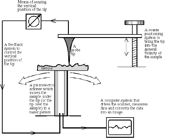
Figure 1. Schematic of SPMs (adapted from http://www.park.com)
The most commonly used AFM
system consists of a cantilever-tip assembly and its force
transducers. The tip is typically made of a silicon or silicon nitride apex
formed by chemical etching, or a bead of a few micrometers in radius, sometimes
called a colloid tip, attached to a thin silicon or silicon
nitride film cantilever. The transducer is commonly made of a position
sensitive photo detector (PSPD) array, as shown in Figure 2, which senses the deflection of a laser
beam reflected off the top surface of the AFM cantilever near the end. The deflection
of the laser beam is generated by the bending and torsional deformation of the
cantilever, which is caused by normal contact and friction forces exerted by
the substrate material surface against the tip.
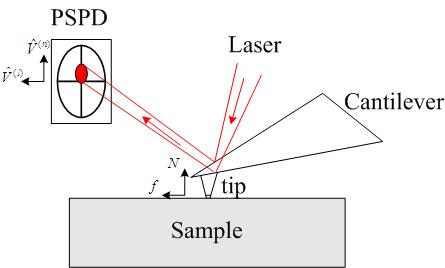
Figure 2. Force sensing of an AFM system
Deformation characteristics of AFM cantilever [top]
To have a quantitative measurement, we need to relate the PSPD output signals:  and and  (in the unit of volts), to their physical origins: normal force (in the unit of volts), to their physical origins: normal force  and lateral force and lateral force  (in the unit of newtons). Intuitively, for a linear system, we need four quantities to convert , to , . (in the unit of newtons). Intuitively, for a linear system, we need four quantities to convert , to , .
  (1) (1)
  (2) (2)
For a long time, people had idealized the situation by ignoring the two terms  and and  . Apparently this is not correct and significant deviations were observed and reported by some researchers, which they called "cross-talk" effect. In order to get a better assessment of the forces involved in AFM system,
many methods were proposed to minimize or compensate the
crosstalk. However, as far as we know, most of approaches didn't
provide a clear and generic analysis on the deformation characteristics
of AFM system; therefore the calibration methods they proposed are
quite limited and sometimes even wrong. . Apparently this is not correct and significant deviations were observed and reported by some researchers, which they called "cross-talk" effect. In order to get a better assessment of the forces involved in AFM system,
many methods were proposed to minimize or compensate the
crosstalk. However, as far as we know, most of approaches didn't
provide a clear and generic analysis on the deformation characteristics
of AFM system; therefore the calibration methods they proposed are
quite limited and sometimes even wrong.
Generally speaking, the crosstalk can be induced
mechanically, i.e. the shear center misalignment
of the cantilever with respect to the geometric center of the cantilever, and
optically, i.e. the misalignment of the PSPD array. For a properly aligned AFM system, the optical misalignment is minimized and the crosstalk coefficient is negligible compared to .
Our analysis shows that:
- the force constants
 and and  are determined by the cantilever spring constants (normal and lateral) and the PSPD sensitivity factors are determined by the cantilever spring constants (normal and lateral) and the PSPD sensitivity factors
- the crosstalk force constant
depends on the mechanical characteristics of the cantilever-tip
assembly (such as the spring constants of the cantilever, shear center of the cantilever along the contacting plane, the tip location and shape, etc), as well as the optical alignment and detection
Detailed mathematical descriptions could be found in our recent paper on the journal of Review of Scientific Instruments.
Principle of D-LFC [top]
Now the main goal is how we figure out a reliable way to calibrate the three force constants , and . According to the above discussion, all the approaches could be cataloged into two types: direct method or indirect method.
Calibrating the
constants based on the measurement of the individual intrinsic
properties of the AFM system, is an indirect method. Evidently, the indirect method has three error sources. One is in the estimation of the torsional spring constant of the cantilever,
another in assessing the effective cantilever-tip structural geometry
parameters, and the last in gauging the angle sensitivity constant of the PSPD. In many cases, the indirect method erroneously
determines the force constants to be an order of magnitude away from their
actual values. Thus, calibration of the force constants based on an indirect
method is very difficult and ineffective.
Calibrating , and
based on (1) and (2), regarding them as constants of system response,
is a direct method of calibration. For this approach, a reference
spring with a known spring constant is needed. Our invention of
the D-LFC makes it possible for the first time.
As discussed above, the principle of the D-LFC is very simple: a
pyrolytic graphite sheet levitated by a strong magnetic field is used
as a reference spring to apply a known force on the AFM cantilever-tip
assembly and by recording the output signals the force constants can be
obtained as a system response.
|